DIY Granite CNC Y Axis Ballscrew Mount Assembly Build Part 2
Posted by Jonathan Gee on Mar 22, 2022
OH HAPPY TIMES!! JUST SOME ALUMINIUM TO DRILL.
Y-Axis Ballscrew Mount Assemblies Part 2
Posted by Jonathan Gee,
22 Mar 2022
This is a privately funded project that frequently sees shortage of funds delaying progress, If you are enjoying this build diary and would like to contribute to the completion of this project and all the future guides and video journeys it would be gratefully received and spent directly on this project. Donate through PayPalMe Here...
Y Axis Granite CNC Y Axis Assemblies Part 2
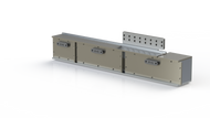
Proposed Y-Axis Ballscrew Mounting Assembly & Cover.
Proposed Y-Axis Ballscrew Mounting Assembly without main covers.
Above you can see the plans for the Y-Axis Ballscrew and Servo Mount Assemblies. There will be two of these arrangements to drive dual Y axis servos and ballscrews. I was excited to get working on these because it felt like this would be quite a milestone and step forward since having a year off hobbying to set up EMG Precision Ltd. I placed the order for aluminium, and it was time to get going.... I purchased my aluminium from Alloy Sales in the UK. The items arrived cut to size with up to a plus 2mm tolerance so there was still going to be finishing work to do to make everything fit nice and square together. As I had done, you must consider the dimensions to allow for and rubber seal strips that you use to minimise coolant ingress. Make sure to use a Vitron type seal and standard rubber will erode with coolant exposure.
Aluminium Delivery for both Y Axis Mount Assemblies.
Paper marking jig for the internally threaded socket mounting positions.
I created a paper jig for marking out and transferring the hole locations to the aluminium. I did this instead of using the wooden jig in the previous step, because the process of cementing the inserts in is not positionally exact all the time. When everything had set, it was very important to have the holes in the aluminium concentric to the granite internally threaded inserts. If you do happen to drill the holes not right you do have the option to open the counterbores to give you a little movement, but this is clearly limited to around one millimetre. Take some time on this step and get it right so you can have a full range of movement for adjusting when it comes to dialling in your machine.
Aluminium Back Plate bolted to the granite side to check bolt clearances and positions.
Brum brum, drill, drill.... Above you can see the aluminium plate offered up to the granite with just a couple bolts holding it. I could then check the clearancee on all the other bolt positions. This backplate was 20mm thick cast, ground aluminium tool plate and I used M8 bolts, the same as the ones used to mount the 30mm rails.
The digital height gauge that was installed on the drill press was used to drill the counterbore depths consistently. This comes in very useful and i really very cheap to buy.
It was nice to be able to markup and set out all of these parts on a 1200mm wide surface plate.
Assembly Lip on the right hand side Y Axis Ballscrew Assembly Back Plate.
Assembly Lip on the right hand side Y Axis Ballscrew Assembly Back Plate illustrating how the unit can be unbolted and slid out for easy maintenance.
Follow the Build on Instagram
Follow the Build on Facebook
Follow Us on LinkedIn
Originally Uploaded On: 22/03/2022
Last Updated On: 22/03/2022
Estimated Date Period: : 15/01/2022
This is a privately funded project that frequently sees shortage of funds delaying progress, If you are enjoying this build diary and would like to contribute to the completion of this project and all the future guides and video journeys it would be gratefully received and spent directly on this project. Donate through PayPalMe Here...
SUBSCRIBE TO OUR BUILD BLOG
Recieve our latest blog posts, build diary updates, weekly releases, offers, guides and more.


 RUB
RUB British Pounds
 US Dollar
 Euro
Euro
 Norwegian Krone
 Canadian Dollar
 Bulgarian Lev
 Polish Zloty
 United Arab Emirates Dirham
 Australian Dollar
 Swiss Franc
 New Zealand Dollar


