Background Part 3- DIY CNC Machine Project
Posted by Jonathan Gee on Feb 26, 2022
EVOLUTION CAN COST A FORTUNE SOMETIMES
EMG CNC
Project Background
[Part 3]
Posted by Jonathan Gee,
26 Feb 2022
This is a privately funded project that frequently sees shortage of funds delaying progress, If you are enjoying this build diary and would like to contribute to the completion of this project and all the future guides and video journeys it would be gratefully received and spent directly on this project. Donate through PayPalMe Here...
Background (Part 3)
Z Design
Pictured above is the Z design that i decided to go with. I went with a 25mm diameter, 450mm long Ballscrew from TBI and Genuine 20mm HIWIN rails and carriages which I purchased through CRD Devices, a distributor for Hiwin. On the build pictures below you will see how i used ground tool plate to strengthen the design and provide side clamping functionality for the rails and the carriages to increase the rigidity.
Maybe because I chose tool steel for the majority of the materials, it was probably at this stage in the planning stage that I probably began thinking about changing my plan to build something much more rigid. The overall weight of this Z axis when completed, even without a spindle, concerned me about using just aluminium extrusion for the gantry assembly. It struck me quite obviously that this assembly would cause flex in aluminium especially under dynamic load.
I don't want to rattle on much longer about my thoughts around the older designs that i had been experimenting with. I will cover the build of the first Z axis and it is really after this stage that i sat back a little and contemplated how i was going to move forward. I would like to get into the nitty gritty of the ultimate direction i chose to go in with Epoxy Granite or Natural Granite as the case turned out to be.
Older Concept Designs
Below is a galley of 16 images of old concept designs that i explored. I have included them as you may or may not gleam some inspiration or direction to help with your own build. Please leave comments or questions though if you happen to find any of these concepts helpful. Many of these designs are perfectly suitable to a range of CNC Router applications. The reason that none of these designs precisely made the final cut, was that the build ethos just continued to grow a tilt towards maximum rigidity regardless almost of weight.
I had this vice laying about that i have previously used for mcikey mouse jobs. I tried it out of the compund table, but, as expected it was completely useless. I very quickly moved to clamping the stock with the hardened clamp fittings. If you shop around you can get a set of these pretty cheap. I found many places selling them for 50-60-70 pounds and more, but i found a full set in Germany for £42 brand new including delivery to the UK. Bargain. And lets face it, they are all pretty much made in the same place. I didn't have any quality anxiety.
Its always nice to have a dry fit and play once you get all your bits delivered. Its good practice to check the obvious functionality and make sure you haven't overlooked something in plain sight. I don't know about you, but sometimes I get computer screen blindnessand miss obvious things. I can't empathise more though how much i reccomended actually having a design plan and working against it. Your design plan may change and evolve mid stage, but tha tis perfectly normal. This will save so many issues and hurdles later on in your build. You should consider things like maintenance access, cable routing, oil pipe routing, access for grease guns, limit switch locations, homing switch. Natural drainage, coolant protection, earhting, It is much harder to accomodate all these things after the fact, and is often the reason a nice looking build ends up with bent metal brackets hanging of an assembly here there and everywher and cable ties fasten to anything that will listen. A little time in the preparation and design stage makes for a much more professional build. If you are not CAD competent, cut out pieces of paper to scale and play around with the layout and fitment. I regularly do this prior to spending time in CAD..
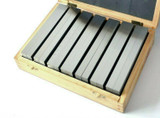
You can see above how the design was intentionally made to assemble with the use of stephensons blocks to aid the spacing and setup. I work only in metric really when it comes to machine design. These blocks are sometimes referred to as 123 blocks. But you can easily purchase metric versions. I have sets of 102030, 15,30, 60, 2550100 etc.. Using these allows for an assemly that will work almost straight from first assembly. Fine tuning to achieve micron perfection can be done later then.
THe stock material choice was designed to be able to assemble a system whereby the rails could be clamped down witht he standard botls, but also clamped from the sides for extra rigidity.
Its not easy to see here, but underneath there is arround 1mm of movement clearance and i would expect no problems here whatsoever. Don't forget to use the plastic fittings to hold all ball bearings in place when you remove a linear carriage. The bearings can fall out and be lost forever quite easily.
IThe back plate of this assembly is ground tool plate so i new that the tolerance would be very close. As it turned out I could fine tune the flatness of the assembly with planning the torquing of bolts.
A little trick i figured out when tapping M5 & M6 holes was to use a setting block as a guide for the tap to ensure that the perpendicularity of the thread was within a degree or so.
Clearly the carriages are placed on the spindle plate here upside down, But I planned to have steel side sections to act as guide and clamping walls for the carriages. These elements also added structural flex resistance to the design. They are not shown in the picture but i used grub screws to side clamp the carriages.
So what did I learn at this stage....
Well i learnt that i am gonna have to have a Part 4 to finish this part of the diary. But also...
Key Learnings....
- When you design your Z axis, i never felt any need to make clearance tolerances of moving components any more than 1~1.5mm. If the design is binding under flex with 1.5mm clearances, you ought to be re-evalting your design. This is obviously different for CNC machines built out of wood, as the timber can easily move, expand and contract a millimetre with temperature and humidity fluctuations.
- .Don't buy cheap and cheerful hardware & taps. You will regret it.
- When tapping many holes, you have to be conscious that the repitive nature of it causes you to worker quicker and more aggressively to in order to finish quicker. This can results in broken taps when you least expect it. Try to focus on actually feeling every single hole you tap. The feedback will let you know if you are likely to break a tap. If you become robotic about repeating the process, you will end up trying to dig a broken tap out of a critical hole.
- Take your time with marking up stock and punching marks for seating your drill bits. If you can use a surface plate of flat surface with a height scribe, this will give you very accurate results.
- if you like to keep all surface finishes as floorless as you can like me. Try using that sticky clear plastic book binding stuff avaialable from anywhere for pennys, to cover and protect your metalwork while you drill holes and move about.
Follow the Build on Instagram
Follow the Build on Facebook
Follow Us on LinkedIn
Originally Uploaded On: 27/02/2022
Last Updated On: 27/02/2022
Estimated Date Period: : Nov 2020
This is a privately funded project that frequently sees shortage of funds delaying progress, If you are enjoying this build diary and would like to contribute to the completion of this project and all the future guides and video journeys it would be gratefully received and spent directly on this project. Donate through PayPalMe Here...
SUBSCRIBE TO OUR BUILD BLOG
Recieve our latest blog posts, build diary updates, weekly releases, offers, guides and more.
THIS BUILD DIARY IS ONLY HOSTED ONLINE BY EMG PRECISION LTD. IT IS A PRIVATE HOBBY PROJECT BY MYSELF, JONATHAN GEE. THIS PROJECT BLOG IS ONLY A DIARY OF EVENTS WITH SOME IDEAS FOR HOW I FELT THE PROCESS WENT WITH SOME TECHNIQUES I FOUND USEFUL. THIS IS NOT AT ALL AN OFFICIAL GUIDE OF HOW TO DO THINGS AND YOU SHOULD SEEK PROFESSIONAL ADVICE FROM COMPETENT PERSONS AND CONDUCT RISK ASSESSMENTS BEFORE UNDERTAKING ANY OF THE TASKS SHOWN IN THIS PROJECT BLOG DIARY.


 GBP
GBP US Dollar
 Euro
Euro
 Norwegian Krone
 Canadian Dollar
 Bulgarian Lev
 Polish Zloty
 United Arab Emirates Dirham
 Australian Dollar
 Swiss Franc
 New Zealand Dollar
 Russian Ruble


